"Space charge" is charge in the dielectric, electrons, protons, and ions, that is moved around by the applied voltage. Charge
tends to build up at "discontinuities" in the dielectric, such as the dielectric-electrode interface in film capacitors, at the grain
boundaries in crystalline dielectrics, and at various molecular sites simply called "charge traps". Space charge is a major factor
in dielectric behavior, such as leakage, high-voltage reliability, and dissipation factor vs. frequency and vs. temperature. Its role
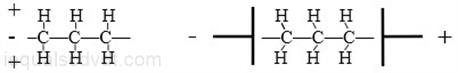
in dielectric aging is still the subject of research. Researchers have shown a special interest in cross-linked polyethylene (XLPE)
because of its widespread use as a high-voltage insulation in power transmission, but work is also being done with polyethylene
napthalate, PMMA, silicon dioxide, and other common dielectrics. Space charge has been extensively studied for many years,
but I don't see many books or journal articles specifically relating space charge phenomena to capacitor behavior. It may be
that capacitor people and dielectric theorists don´t talk to each other much. It may also be that the really ground breaking
papers on space charge and capacitors are from the 1950s-1970s are remembered today by physicist and not by electronics
people. They are also mostly paywalled at $40 each.
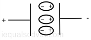
Dielectric absorption (DA) is easily understood in terms of space charge. When a capacitor is charged, electrons (-) in the
dielectric are attracted to the (+) electrode. When the capacitor is shorted, the electrons are slowed down in returning to their
holes by the dielectric´s high resistance. This gives the appearance that the capacitor is still charged, and in a sense, it is.
Space charge also explains why some capacitor reliability factors, such as breakdown voltage and corona starting voltage, tend
to correlate with the peak-to-peak applied voltage better than with the peak applied voltage. It's almost as if the capacitor
somehow remembers the voltage applied to it in the past, and adds it to the voltage applied now. In fact, the capacitor does
have a memory in the form of space charge.
The tendency for high-voltage capacitors in DC operation, to fail when voltage is reversed is one example. When the applied
voltage is suddenly reversed, previously displaced charge in the dielectric now adds to the voltage stress. There are others.
Corona may more easily start when an AC waveform is applied than when a DC voltage is applied, even when the DC voltage
is higher than either of the AC peaks. For example, 1000 VDC is less likely to start corona at a void in a capacitor dielectric
than is +750 volts quickly followed by -750 volts, all things being equal. This complicates high-voltage capacitor design in that
you must not only know the highest voltage your capacitor will see, but how it will be applied.
The breakdown voltage of polymers is highly time dependent. As the electrons move under the influence of the applied voltage,
charge accumulation can cause voltage stress that in some spots, will be several times that of the applied voltage alone. The
isolation voltage of opto-isolators for example, may be rated both steady-state and after one minute. Capacitors are often rated
both steady-state, and "surge".
Space charge probably also explains why the breakdown voltage of polymers is nonlinear with thickness. Above about 5-10
mils, breakdown voltage increases roughly as the square of the thickness. Presumably, the thicker the insulation, the more
space charge can accumulate. There have been reports that layered polymer insulations have a higher breakdown voltage than
if they were made of just one solid piece. One reason this is done with capacitors is make reduce the likelihood of failure from
defects in the film. It is unlikely that a defect in one layer will line up with a defect in the next layer. However, layering may also
help keep the space charge more evenly distributed throughout the insulation. In some high-voltage capacitors, the dielectric is
broken up into two layers with a floating foil or metallization layer between them. This is to increase corona starting voltage.
Breaking up the dielectric into more layers would presumably increase breakdown voltage even more, without increasing total
dielectric thickness. There is apparently some research in this area.
Dielectric absorption:
Dielectric absorption (or DA), sometimes called "soakage", "voltage retention", "restriking voltage", or "remaining voltage". In
high-voltage power cables it's called "return voltage". A capacitor, once charged, stubbornly retains part of the charge, even
after being discharged (shorted for some number of seconds), as if it had "soaked" into the dielectric. DA is modeled as an
infinite series of RC networks in parallel with the primary capacitance, where the Rs are mostly very large and the Cs are
smaller than the nominal capacitance. DA is a source of error in precision integrators and sample-and-hold circuits. Large
high-voltage oil-filled capacitors (exceptionally high DA) can be shorted, yet retain enough charge to be dangerous. They are
normally shipped with a short across the terminals that should not be removed until the part has been installed. High-voltage
capacitors in traditional TV sets are also still dangerous after being discharged, as is the parasitic capacitance in large oil-filled,
high-voltage transformers and some high-voltage cables.
There is a standard test for DA. The capacitor is charged to some voltage for one minute (often 100 volts, but others can be
used), and is then shorted for two seconds. After one minute, the recovered voltage on the capacitor is read using a very high
impedance meter. The DA is expressed as the ratio between the recovered voltage and the charging voltage, in percent. MIL-
C-19978D calls for a 5 minute/5 second/1 minute sequence. These tests are useful for comparing dielectrics, but don't really
tell you just how a capacitor will perform in your application. In particular, the difference in DA of various dielectrics as seen
one minute after the short is removed does not necessarily precisely correlate with the difference in DA as seen in the first few
10s of ms. In general, Teflon, polystyrene, and polypropylene are the best (as low as 0.02%), while the electrolytics, high-k
ceramics, and oil-filled are the worst (1% on up). Impregnated film caps tend to have a DA that reflects the impregnant more
than the film. Given the RC model for DA, it would make sense that the dielectrics with the highest insulation resistance (which
also tend to have the lowest dielectric constant) would have the lowest dielectric absorption. There is also a significant
difference from part to part. However, while the RC model is useful for predicting how DA will behave, it does not reflect the
underlying physics. See: Miscellaneous page. Also see: http://www.national.com/rap/Application/0,1570,28,00.html
For more information see: Space Charge in Solid Dielectrics, ed. Fothergill and Dissado. 1998, ISBN 0 9533538 0 X
This is a guide to measuring it.
1) The the test capacitor (C) is charges at some voltage for a number of minutes (Tc). The charging time might be one or
more minutes. Some people say one minute.
2) The Charging Switch is opened, and the Discharge Switch is closed, for perhaps 10 seconds (Td).
3) The Discharge Switch is opened and the voltage on C is monitored with a DVM or oscilloscope for several minutes
(Tm).
4) The ratio between the original voltage and the final voltage is calculated, in percent. This is the dialectical absorption
number.
The circuit below has everything you should need for a DA measurement. The two 100 ohms resistor are limit the charging and
discharge current to levels that won't damage the capacitor C or the switches. If the test voltage you use is high enough to
damage the meter or (more likely) the scope, the 10K and the zener diode should protect it. Why bother? If you are using low
DA caps in a circuit you might actual need to measure the DA. DA varies significantly part to part and batch to batch. In fact it
varies enough to cause some doubt about the exact DA numbers given to various dielectrics.
One reason for the disagreement in DA numbers is that the standard test will give different numbers depending on the capacitors
usage history. Standard tests should take this into account.
The DA of a dielectric material tends to be proportional to the leakage figure. This suggests that the DA number you get might
be different for a higher voltage capacitor than lower voltage capacitor, assuming the test voltage is the same. A good
experiment to try, but I don't know that anyone has. There have been reports that the DA of ceramic opamp packages can
cause problems for some analog circuits.
If you found it necessary to build a super low DA capacitor in the 0.001-0.1 uF range, how would you do it? Vacuum makes
the highest resistance dielectric, followed by gasses. These would be very difficult to work with. There are various metallic
oxides that have very high resistance and these might have possibilities.