Reliability Issues

Certain factors affect almost every type of capacitor: Operating temperature, ripple current, inrush current, operating voltage. When in doubt, consult with the manufacturer to avoid misapplication.
Surface mounting has brought additional problems. In the case of ceramics, the problems and their solutions are well documented. For tantalum and aluminum electrolytics however, hard numbers on reliability are more difficult to obtain. Users claim more problems with the electrolytics both as a group, and with individual batches. SMD tantalums seem to have more long-term failures due to shorts than their through-hole equivalents. SMD aluminums are getting a bad reputation for long-term failures from leaking electrolyte. This may correlate more with the very small size of SMD aluminums than the fact that they are SMD. My own limited experience with SMD film capacitors suggests that they may be more failure-prone than their through-hole equivalents. This paragraph is five years old. Things may have changed.
Film:
Film capacitors are common in high voltage/high current applications like DC link, power distribution, and motor run. Capacitor reliability and life-span are major considerations in the design of these systems. Operating voltage as a % of rated voltage, and operating temperature are the major considerations. The manufacturers will have information for reliability under different conditions. Also, see EIA-456-A below.
Low-voltage board-level film capacitors are more or less expected to last the life of the product. The only really flagrant reliability problem I have seen is with stacked-foil capacitors. The leads are attached to the ends by soldering or spot welding. A few manufacturers have had trouble doing this reliably and I have seen the occasional lead fall off the un-potted variety (potting would just hide the problem). WIMA and ITW seem to be among the trouble-free. I would be happy to hear of any other experiences.
The expected life of a film capacitor is dependent on a number of factors, which generally apply to paper-oil capacitors as well. Many of the causes listed below apply mainly to high-voltage capacitors where life problems are of the greatest concern. This list is hardly complete:
Voltage stress: Electrons, in the form of leakage current, collide with polymer molecules causing them to break down. Given time, the dielectric will fail. Any kind of defect in the film or between windings will speed this process by creating voltage gradient "hotspots". The defects may actually be required to cause damage. It is believed that in high voltage AC applications, UV light generated by charge movement deteriorates the dielectric. This has been observed in clear dielectrics like unfilled polyethylene, and no doubt happens in opaque ones as well .
Corona: The worst form of voltage stress is "corona", a current flow in ionized gas in a void, either in the dielectric, or between layers (see below). Corona does not constitute a true voltage breakdown, but once corona starts, rapid deterioration of the polymer will lead to breakdown. Corona is similar to "partial discharge", except that corona, by definition, always involves the emission of light and partial discharge may not. Some dielectrics, like polyethylene and Teflon, are more vulnerable to corona than others (mica).
Moisture: Moisture absorption accelerates damage from voltage stress. This can be a huge problem for cheap Chinese capacitors which might be manufactured with moisture inside or be too poorly sealed to keep moisture out over time. Some film dielectrics, like polycarbonate and polysulfone tend to absorb more moisture than others (polypropylene and polystyrene).
High-voltage pulses and voltage reversal: Stress on the dielectric depends on how fast voltage it is applied, as well as its magnitude. For example, when the voltage applied to a high-voltage DC capacitor is reversed, accumulated charge in the dielectric (called space charge) adds to the voltage stress. This must be allowed for in certain applications. Space charge is implicated in all sorts of capacitor behavior and failure mechanisms. Many high-voltage capacitors are designed for pulse operation. As far as I know, there is no rigorous way to calculate reliability. Manufacturers apparently depend on testing and experience.
Thermal stress: Elevated temperatures will cause a slow deterioration of the dielectric, especially film.
Contamination: Because the film is often only microns thick, microscopic metallic particles can cause shorts between the conductive layers. This is caused by less than perfect clean-room conditions in manufacturing. The short will not necessarily occur at the time of manufacture, but can occur hundreds or thousands of hours later when cold flow has allowed the particle to penetrate the film. Strong solvents can cause damage or at least to the markings.
Film defects: Thin spots, pinholes, cracks, voids, and impurities in the film can cause early failure. Because these are just about impossible to avoid in ultra-thin plastic films, film capacitors are often wound using several thin film layers instead of one thick one. It is unlikely that a pinhole or other defect in one layer will line up with a defect in another layer. Oil impregnation greatly reduces the problem.
Voids in the windings: Voids in the windings, like voids in the dielectric, cause higher than normal voltage stress, and points where corona or voltage breakdown can more easily occur. This can also be mitigated by oil impregnation, which can greatly increase the voltage need to start corona.
Operating temperature: As a rule of thumb, capacitors tend to double their failure rate every 10-15C increase in temperature. This is a big deal for big AC capacitors because internal losses will increase the internal temperature. Temperature cycling can also increase the failure rate.
Altitude: For big AC power capacitors a high altitude reduces cooling.
Other problems: Film capacitors tend to fail by shorting, but some defects can cause other kinds of failures. Poor lead attachment can cause opens for example.
Note that these are all great simplifications. Whole books are written on the complex mechanisms of dielectric deterioration (aging) from high voltage, for example.
A generally accepted formula for estimating film capacitor life is:
L=LR*(ER/Eo)7*2(deltaT/10)
Where:
L = operating life under stated temperature and voltage
LR = life at rated temperature and voltage
ER = rated voltage limit
Eo = operating voltage
deltaT = difference between rated operating temperature and capacitor core temperature in C.
Ceramic:
Early multi-layer types had problems with layers separating, but today's ceramic capacitors seem very reliable. However, board assemblers still complain of the occasional batch of SMD capacitors that is prone to shorts due to cracking during soldering. In general, ceramics seem much more likely to fail short than open. SMD ceramic capacitors are strong but brittle, and this makes them susceptible to failure during soldering and from temperature cycling, due to mismatch between the temperature coefficient of linear expansion of the capacitor and that of the board. Ceramic capacitors with a large thermal mass can be a problem because they heat up slower than the board does.
Flexing of large circuit boards can be a problem for large ceramic capacitors; smaller capacitors. This may be caused by breaking up of the web or the mounting of additional components after the SMD parts are soldered, especially components installed by hand (heatsinks or spacers for example). Fixtures that minimize stress on the board will usually prevent this. Thicker board material may help, as will locating components away from areas of greatest stress, such as close to board edges or near connectors.
Designers will generally want to use the smallest size capacitor possible. In general, the shorter the capacitor is, the less the stress will be. Size 2225 is about the upper limit for leadless ceramics with reflow soldering, and 1812 for wave soldering. Also, parts that are wider and/or taller will be stronger and less likely to crack. However, smaller sizes can still have problems, especially if a lot of temperature cycling is encountered, so designer usually prefer parts no larger than 805. Some manufacturers have redesigned their older boards to use smaller capacitors to eliminate chronic cracking problems. Using just the right amount of solder also helps. The solder joint needs a little flexibility, and too much solder makes the joint too strong to flex. Sorry to say I have seen this problem on American-made boards more often than on Chinese. Very large SMD ceramic capacitors have lead frames and are much less bothered by thermal mismatch and other stresses. Lead-frame ceramics are larger and more expensive however, and have a more limited history.
These problem has greatly lessened over the years, however. Board designers, board assembly houses, and equipment makers have a better understanding of the factors that contribute to reliable surface-mount soldering, such as pad (land) size, solder type, heating profiles, and other factors. Capacitor makers have also learned much about the subtleties of manufacturing their products that contribute to better reliability. More recently, manufacturers are using better solder caps with more flexibility.
One limitation on the life of a ceramic cap is oxygen migration while under voltage. The rate of migration is dependent on voltage and temperature and eventually leads to a fatal reduction in breakdown voltage. In normal use this may not be a significant cause of failure, except at high temperature, but is very useful for accelerated life testing.
Another potential problem is high humidity, mostly for ceramics made using silver.
A generally accepted formula for estimating ceramic capacitor life is:
L=LR*(ER/EO)3*(TR/TO )8
Where:
L = operating life under stated temperature and voltage
LR = life at rated temperature and voltage limits
ER = rated voltage limit
EO = operating voltage
TR = rated temperature limit
TO = operating temperature in C (usually assumed to be same as ambient)
With no serious wear out mechanisms, ceramic manufacturers claim vanishingly low failure rates if the parts are not abused. However, for those unwilling to take this on faith, a technology call "acoustic micro-imaging" makes it possible to inspect ceramics for voids and other defects before they are used. I have no information on the reliability of this technology however.
A number of companies do this sort of thing, not just on capacitors but all kinds of electronic devices and assemblies:
http://www.sonoscan.com/index.html Prominent company in the business. They have excellent pictures on this site.
In the last five years, short-term reliability of barium titanate based ceramic capacitors (type 2) has become a matter of some concern. It has been long been assumed that the lifetime of ceramics could be measured in centuries. As the dielectric layers have increased in number and the thickness has decreased, accelerated life testing has shown a decreasing life span. While the increasing number of layers is a part of this, the main problem seems to be the increasing voltage stress on the dielectric (measured in volts/cm). In 2000 it was around 5000. In 2010 it was more like 35000 V/cm. This may be a matter of small defects in the dielectric that were not a problem in older parts.
Electrostriction:
Electrostriction is the expansion and contraction of a dielectric material caused by the application of an AC voltage. It's most commonly associated with the higher K ceramic materials. Electrostriction has been known for many years. Under the right conditions, a ceramic capacitor can be made to "sing" but that has rarely been a reliability or performance issue. With modern SMD ceramic capacitors however, it can be. Because SMD capacitors are "clamped" at the edges, the capacitor bends in the center and can eventually crack. This is most likely in large ceramics under a significant AC voltage and which are expected to operate continuously for 10s of thousands of hours. Murata, for one, has SMD ceramics with special construction for reduced electrostriction.
Aluminum Electrolytic:
Aluminum electrolytics have a reputation for being troublesome in some electronic equipment. NASA, for example, does not allow them to be used in flight hardware because of the risk of failure and outgassing. Tantalum capacitors can be used instead. There has been some work in designing aluminums that could be used in space applications however.
In general, close attention has to be paid to their application if you expect good long-term reliability. The higher the operating temperature the shorter their life, and running aluminums too hot seems to be a common design mistake. This can be caused by things like excessive ripple current, poor ventilation, too high a system ambient, and/or locating them too close to a hot power supply component. Over time the oxide film tends to dissolve into the electrolyte and every 10C rise in temperature doubles this effect. The rate of deterioration is much faster in storage than if the capacitor is kept voltage biased in normal use. Actually, the most common failure in aluminum electrolytics (at least for through-hole aluminums) is not loss of capacitance or leakage, but increase in ESR, due to loss of water from the electrolyte. This is also temperature dependent. Operating life is less dependent on operating voltage than with some capacitors. A generally accepted formula for estimating electrolytic capacitor life is:
LT=LR*(ER/EO)*2(deltaT/10) liquid electrolyte
LT=LR*10(deltaT/2) polymer electrolyte (from Illinois Capacitor)
Where:
LT = operating life under stated temperature and voltage (capacitor core temperature, not just ambient)
LR = the life at rated limits
ER = rated voltage limit
EO = operating voltage
deltaT = difference between rated operating temperature and capacitor core temperature in C
Note the use of "core temperature" rather than ambient. Big aluminums are usually used in applications involving high ripple current, which causes self heating. Their wound paper/foil makes electrolytics poor at dissipating heat. Wattage dissipation in a capacitor is equal to I2*(ESR), where I is the ripple current, and ESR is equivalent series resistance at the frequency of interest. The manufacturer may not give you the ESR data however. Instead they might give a number for "allowed ripple current". A rough idea of temperature rise can be found from power dissipation, surface area of the capacitor, and the amount and kind of cooling available (forced-air, convection). Some manufacturers can provide specific guidelines. Nomographs exist for this sort of thing, but are hard to find.
Some people make "capacitor coolers", heat sinks made to clamp around the bottom of large aluminums.
http://www.aavid.com/product-group/capacitors/capcoolers For 3" diameter capacitors.
See:
"Selection and Application of Capacitors"
Both tantalum and solid-electrolyte capacitor makers claim longer life than conventional aluminum capacitors. However, choosing the right aluminum electrolytic with the right deratings, will often allow you to meet whatever longevity requirement you have in most common applications without resorting to more exotic (and expensive) parts.
Parts kept in long-term storage (2-3 years or more) may have very high leakage when first used and should not be subjected to full rated voltage (and should be current limited) until the leakage falls to normal. Reforming of the dielectric can be done by applying a voltage that is slowly increased to maximum over a period of several hours, with current limited to rated leakage current. Some manufacturers have published such elaborate recommendations for reconditioning capacitors after long storage that it seems easier to just buy new ones. However, while common wisdom has it that storage is very bad for aluminum capacitors, manufacturer's literature does not always support this. One manufacturer has a 1000 hour/85C shelf-life test that specifies that leakage will not exceed that of a new capacitor. That's equivalent to about 7 years at 25C. It may be that modern capacitors are less susceptible to storage problems than older ones.
See:
MIL-HDBK-1131 Storage Shelf Life and Reforming Procedures for Aluminum Electrolytic Fixed Capacitors
It´s on the web in PDF form.
Unless epoxy sealed, aluminum capacitors can receive long-term damage from chlorinated solvents, and from halides in general. When in doubt, use a non-chlorinated board cleaner. Some manufacturers even warn against chlorides in no-wash solder flux (including some that claim to be chloride-free), board coatings, and adhesives. Methyl bromide, a very common fumigant, is suspected of causing capacitor failures in at least one case. Some non-chlorinated solvents can cause damage to the rubber end-seals if exposure is too long. Manufacturers also warn against other chemicals like hydrogen sulfide and ammonia.
Don't subject aluminum capacitors to more than about 1.5 volts reverse polarity at 25C, and more than about 0.4 volt at 85C .
Large axial-leaded electrolytic capacitors have problems with leads breaking from vibration and must be held down with glue or a cable tie.
Manufacturers usually warn against using general-purpose aluminum capacitors in applications involving high surge currents. Although aluminum capacitors are not as vulnerable to surge currents as tantalums are (see below), possibly because higher ESRs help limit the current, they may not be reliable in such applications. Use capacitors with specified high-current and/or dV/dT ratings such as photoflash aluminum electrolytics.
So how do you know when an aluminum capacitor has reached its "end of life"? The common rule is when the capacitance has dropped by 20% or the ESR has doubled.
XXXXXXXXXX
A problem rarely mentioned is the quality of many Chinese parts in general. Aluminum electrolytics are high-volume, low-margin parts and if the small Chinese regional producers expect to compete with Japan and the larger Chinese companies they must cut costs to the bone.
The low cost of Chinese labor is not enough, their competitors are generally much more automated with the Chinese using older second-hand equipment.
So how can they compete?
Use lower purity aluminum for the case and foil. This can result in cracks when the case is formed and corrosion in critical places.
The use of cheap natural rubber plugs instead of synthetics like EPDM. This can result in early loss of water from the electrolyte and even leakage.
Use lower cost plated foil. Instead of foil with a 10-20% voltage margin, use 25V foil for a 25V capacitor.
Dilute the electrolyte with extra water.
Reduce equipment maintenance. It take time and expertise the Chinese do not always have.
Little product quality control. Again, that takes time and money.
The result is parts with lower reliability and shorter life. It's hard for the user to know. Testing aluminum capacitors is not easy. You can use a cheap LCR meter to measure the uF value. A good LCR meter (expensive) will tell you the value and things like dissipation factor and ESR, but life testing requires thousands of hours and expensive equipment.
I have noticed that a few Chinese manufacturers of cheap electronics, like audio boards, say they use Japanese electrolytes.
XXXXXXXXXXXXXXX
Recent news:
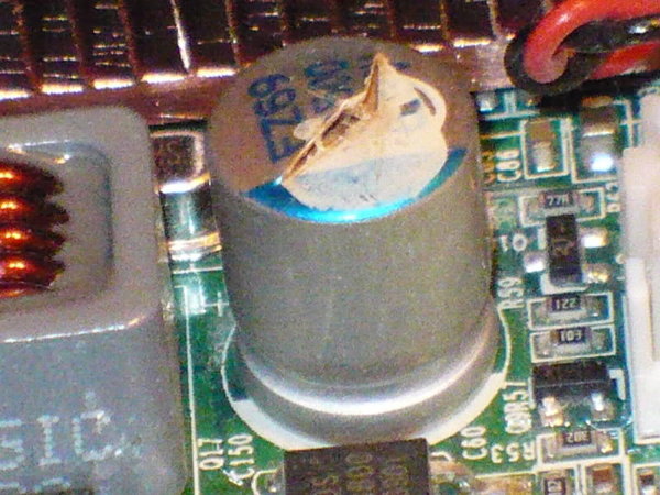
There are many reports of high failure rates/short life of aluminum electrolytics made by a number of Taiwan companies. It seems they all purchased a novel high water content, low-ESR electrolyte from the same source. The formula was defective (industrial espionage gone wrong) and the electrolyte evolves excessive hydrogen, which causes the cases to leak or even burst over time. However, the caps may be unusable even if they look normal. There also is corrosion of the aluminum caused by the electrolyte pH being too high. Time to failure is said to be from a few hundred to a few thousand hours. The number of companies involved is estimated to be more than a dozen, few of which admit to any problem with their parts, but blame the design of the final products. Names most often mentioned include Jun Fu, Choyo, Chhsi, Luxon, Evercon, Sacon, Lelon, Licon, Tayeh, Capxon, Jackcon, JPCON, and Rulycon, a shameless ripoff of the reputable Rubycon brand. Some brand names are actual companies, but others are fictional brands made by companies who didn't want to put their names on these products. Some companies seem to have changed their names several times. Teapo and Jamicon, also sometime mentioned, say they got their electrolyte from Japan and never had a problem.
The problem seems to have started around 2001 and peaked in 2002, but a number of motherboard repairmen say they are still seeing defective capacitors on current production products, including major brands. In fact, defective capacitors may still be in production as of 2006. To make things worse, there are, as always, many poor quality and counterfeit parts coming out of the Far East. Many products can be repaired by just replacing the capacitors, but in some cases the capacitors cause the voltage regulators to fail as well. It may be safest to stick to Japanese brands from authorized distributors.
The parts have been widely used on white-box PC motherboards and in many other products. Products sold (but perhaps not made) by major companies are involved as well, IBM, Apple, Dell, HP, Samsung and others. Why? The difference in cost between a brand name part with a history and a no-name part is pennies. The ASUS motherboard I just bought uses all Japanese electrolytics. A few companies, IBM, the PC board maker ABIT, and capacitor maker Jackon, for example, have "come clean". Other companies deny everything to the point of threatening people with lawyers.
This has worked well for some technically savvy people. A small cottage industry has grown around recapping motherboards and recapping kits that contain the right kind of capacitors in the right sizes. Other people obtain bad electronics hardware for very little money, if not free, and change out the bad capacitors. Next thing you know, you have a 48" TV for the bedroom for a $4 investment. Getting the right size capacitors for odd products can sometimes be a problem however.
For more information see below. Other links I had have gone 404:
XXXXXXXXXXXXXXX
Tantalum Electrolytic:
As with other capacitors, operating temperature and operating voltage have an affect on service life and reliability.
Most tantalum capacitor types tolerate a limited amount of reverse polarity voltage. Manufacturers recommend no more than about 1 volt at 25C and 0.1 volt at 125C, others say no more than 10% of rated voltage at 25C and 1% at 125C. Experience shows that solid tantalums inserted backwards in low-voltage systems (a 5 volt buss for example) are unpredictable and may take from seconds to years to fail. The time to failure is much less at elevated temperature however, and the parts should failure quickly in routine quality control temperature testing.
Solid tantalum capacitors tend to have a problem with surge currents due to impurities and thin spots in the dielectric. Manufacturers typically recommend at least 1 ohm of series resistance per operating volt if the inrush current is not otherwise limited. Tantalum capacitors should not generally be used for power supply filtering unless specifically made and tested for the application (as some are). If you do use a general-purpose tantalum in a power supply application, derate the operating voltage by at least 2:1 (some say as much as 4:1, depending on application) if possible and/or use soft-start circuitry. Tantalums are often used as output filters for IC voltage regulators in small systems and the regulator will probably limit the turn-on current to a reasonable level. A tantalum on the input side of the regulator may be more vulnerable however. The progressive miniaturization of modern electronics has brought tantalums into more applications where surge is a problem, where a larger aluminum capacitor would previously have been used. A 3 or 4:1 voltage derating has a drastic impact on volumetric efficiency, so manufacturers have had to improve their manufacturing and testing methods. Leakage testing helps catch tantalums with dielectric defects. They sometimes do 100% surge screening to weed out early failures as well. Complaints of tantalums catching fire are common, SMD more often than through-hole. Manufacturers only recommend 20% voltage derating for PEDOT tantalum capacitors.
Some ceramic capacitor makers have specifically targeted SMD tantalums for replacement by large ceramics. This is partly in response to the dissatisfaction of some equipment makers with the reliability of SMD tantalum bypass capacitors (through-hole tantalums seem to be much less troublesome). Problems with tantalums may be vendor specific, but ceramics do have some advantages over tantalums in general. Ceramics are not polarized so there is no fear of putting them on your board backwards. Other advantages are lower ESL and much lower ESR for a given capacitance. In many applications, ESR is more important than bulk capacitance, so a large tantalum can often be replaced by a relatively small ceramic. Ceramics generally fail by shorting however, and can burn your board, just like a tantalum.
Unlike aluminum capacitors, solid tantalums have no significant shelf-life restrictions, but I have heard that long-term moisture absorption can impair self-healing.
Small-value tantalum capacitors are sometimes used in analog circuits, such as for a cheap (and small) way to get very long filter time-constants. Some manufacturers even recommend this. This is risky. Most samples may show acceptably low leakage but a few percent will be much leakier than average and manufacturers will not usually guarantee leakage to a low value. Large-value ceramic capacitors (Class 2 and higher) will also have this problem. It will be OK in some applications, but when in doubt, use a film cap.
Wet-slug (and foil) tantalums use a sulfuric acid electrolyte and have their own problems. Cheaper wet tantalums have silver cases and are sealed with Teflon. The reliability of silver-case tantalums has always been problematical. They have almost zero tolerance of reverse bias because the silver grows dendrites that cause rapid damage. Also, the Teflon seal can allow the slow loss of electrolyte, or even outright leakage. Hobbyists should beware of old military-surplus parts. Better quality wet tantalums have tantalum cases and tantalum-glass seals. Leakage is much less of a problem, and they can tolerate several volts of reverse bias. Wet tantalums will not fail by going up in flames.
The expected failure rate of a solid tantalum capacitor is dependent on both operating voltage and temperature. One formula for estimating solid tantalum capacitor life is:
LT=LR*(ER/EO)3*2(deltaT/10)
Where:
LT = failure rate under stated temperature and voltage
LR = the failure rate at rated limits
ER = rated voltage limit
EO = operating voltage
deltaT = difference between rated operating temperature and actual capacitor temperature in C
Note the relatively high dependence of reliability on operating voltage, compared to aluminum electrolytics.
Using the formulas:
Numbers for LR, ER, and TR are obtained from the manufacturers data sheets. LR is almost always given for aluminum electrolytic capacitors, and sometimes for tantalum. LR is less commonly found in manufacturer literature for other types unless they are designed for special usage. Note that the formulas do not allow for high surge-current operation. A further complication is that a "failure" might be defined as specific loss in performance that might or might not be of interest in your application, rather than a catastrophic loss of function. This especially true for electrolytics. Manufacturers are not in complete agreement as to these formulas. For example, some say that different shaped of electrolytics should have different lifetimes, all other things being equal.
LR is typically given as 1000 to 5000 hours. This does not sound like much, but remember, it is for worst-case conditions and goes up rapidly for reduced temperatures and voltages. The magic word here is "derating". The further below its maximum rated voltage and temperature you use a capacitor, the longer you can expect it to last. For film and electrolytics, the expected life will roughly double for every 10C below rated maximum operating temperature (a rough but useful approximation). For many applications, with conservative deratings, many designers will not find it necessary to run the numbers. However, some instrument makers take the opposite approach, documenting the stresses on every component and calculating expected reliability.
EIA-456-A:
This is a test for the evaluation of the long-term reliability of AC metallized film capacitors used in power applications, motor run, power factor correction, and others. This standard calls for a HALT style test (Highly Accelerated Life Test). The test conditions are simple enough:
Voltage: 125% of rated voltage.
Temperature: Rated temperature + 10C.
These conditions cause aging at a rate of about 30:1. So, if the test lasts 2000 hours, the capacitor sees the equivalent of 60,000 hours of normal operation (about 6.8 years). The test calls for a survival rate of 99.5% at the end of one year and 94% at 6.8 years. Is this important? If a home owner has to replace a run capacitor in their central air, they are in no position to evaluate various brands. If you are building central air, you need to run this test to control warranty costs. There is a huge difference in the life of different brands of capacitors. Actually, if you buy American (or at least North American) you should be safe, in my opinion. Buying obscure Chinese parts is just asking for trouble.
http://www.gideonlabs.com/ These guys are specialists in failure analyses of electronic components.
http://www.badcaps.net/ The motherload of "bad cap" stuff. Sells caps and cap kits for motherboard repair. Includes a list of known bad brands (about 30) in the Forums section.
http://www.electronicproducts.com/Engineering_Calculators_and_Tools.aspx