
My humble opinion:
There are any number of ceramic materials used in capacitors, but there are only a few I ever use.
C0G for typical applications, the best performing ceramic and only pennies a part more than others. Larger than others
however and not available in very large values. Suitable for timers, oscillators, filters, etc.
Temperature compensating ceramics, also Class 1. I have personally never needed them.
X7R, the best of the Class 2. These are mostly for bypass applications, or whenever you need a small part but can get
along without the performance of C0G.
Lots of other parts are made and for good reasons, but their performance is such that they must be used with some care.
Standards:
American: EIA RS-19
European: IEC-60384
Japanese: JIS C5101
The ceramic dielectrics are made of a variety of titanates, zirconates, and oxides (and many other things as well). Common
ingredients include titanium dioxide, barium titanate, and strontium titanate. The exact formulas for the various ceramics differ
from one manufacturer to another. The EIA classifies the ceramics into four classes (1-4), and into types within those classes.
The lower the class number, the better the overall characteristics, but the larger the size for a given capacitance. Types within
each class define recommended temperature range, temperature drift, and tolerance on the expected temperature drift. Other
parameters are less well defined. However, the EIA does provide guidelines as to how they will be measured. These include
insulation resistance, dissipation factor, quality factor, voltage dependence, and a host of environmental tests, such as thermal
shock, moisture resistance, and flammability. Generalizations about critical parameters can usually be made about the various
types with good reliability, even when not stated. In some cases however, you will have to look to the manufacturer for data.
Class 2 and 3:
Class 2 and 3 ceramics (class 4 has officially disappeared) have been typically based on barium titanate (Ba2TiO3), although other materials are coming into use. They have problems not seen in Class 1 and film capacitors, including very poor temperature drift, high voltage-coefficient-of-capacitance and, high voltage-coefficient-of-dissipation factor (all of these are different for AC and DC), high frequency-coefficient-of-capacitance and a significant aging rate. The higher K material, > X7R were once considered to be too unreliable to be used in critical applications, but quality is much better today. These capacitors age because the crystal structure they have when they are made slowly changes to another, lower K form, over time. The crystal structure can be be changed back by heating for several hours at 125C to 150C. After cooling the aging starts all over again.
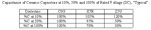
Applied voltage affects some properties so much that these capacitors are normally characterized at no more than 1 volt AC or DC. Because these affects are all more dependent on applied voltage vs. maximum voltage (volts per thickness in other words) than on the absolute voltage, you can try using the highest voltage part possible, size permitting. The table below shows what happens to capacitance when DC voltage is applied to various ceramics. Capacitance vs. AC voltage, and D. F. vs. both DC and AC voltage go through more-or-less similar contortions. The numbers are approximate at best. They will vary considerably with the temperature, actual rated voltage, and with manufacturer.
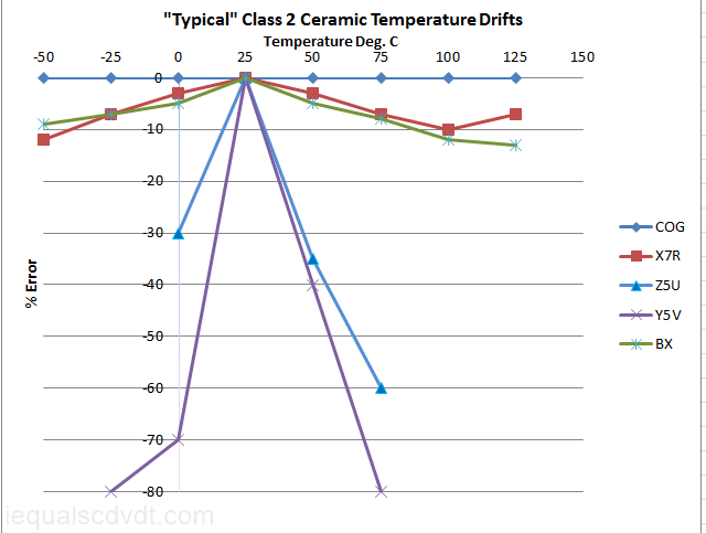
These capacitors don´t have the good high frequency characteristics of Class 1 ceramics, they all show a drop in capacitance and a rise in dissipation factor as they go above 1 MHz. However, some high-voltage/high current RF capacitors are made of the better Class 2 ceramics, for use in the 1-40 MHz range. High-K ceramic capacitors can show significant piezoelectric effects; if you tap them they will produce a voltage spike. This is caused by the barium titanate, the main material in high K ceramics. The higher the K, the stronger this affect. This can cause problems with circuitry dealing with low-level signals, making them vulnerable to mechanical shock. This is another reason to use Class 1 ceramics when designing analog circuitry. Class 2, and higher, ceramics do have an advantage in size, however. In fact, high-K ceramics can compete with electrolytic capacitors in many applications where low ESR is more important than bulk capacitance. The graph on the right showes the "typical" temperature stability of the most popular higher class ceramic capacitors, with C0G as a reference.
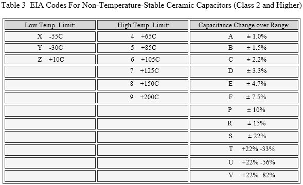
The table below shows EIA codes for non-temperature-stable ceramic capacitors and specifies temperature range and capacitance drift tolerance over that range.
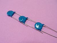
Multilayer Ceramic Capacitors:
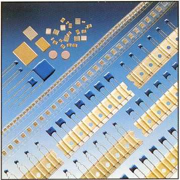
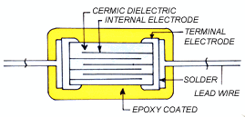
The construction of ceramic capacitors have changed dramatically over the last few decades. At one time, the common form was that of a single-layer ceramic disk. A metal layer was screened and fired on each side, and wires soldered on. This was fine for making 1000 volt/0.01 uF capacitors, but with the decline of the vacuum tube, demand for such parts has likewise declined. There is still a place for them, but not inside a cell phone or laptop computer. Today's electronics requires ever more capacitance in a smaller volume. The way to get it is with the "multilayer ceramic capacitor" (MLCC). MLCCs are made by screening many very thin alternating layers of unfired ceramic and silver-palladium alloy electrodes, and firing the result to make a finished capacitor. The dielectric layers may be >30 microns to <5 microns. Newer versions of end caps, called "flexible", a layer of silver filled epoxy, improve reliability.
SMD ceramics are made in astonishing numbers, 100 billion/year is one number I have seen (2008).


Class 1:
Class 1 ceramics include C0G (sometimes called NP0 which is actually from a very similar MIL standard), and temperature compensating capacitors. They were first based on titanium dioxide, and later on barium neodymium titanate (other materials are also used) but can have low levels of barium titanate, calcium titanate, and other things added to increase the dielectric constant, or to get a desired temperature slope. CaZrO3 is increasingly being used. There are a lot of innovation out there, especially from the microwave folks. C0G capacitors have many of the advantages of film capacitors plus very low temperature drift (limited to ±30 ppm/C over -55 to 125C), including very low aging, voltage coefficient, frequency coefficient, leakage, and dissipation factor. C0G capacitors are used into the GHz range. Dielectric absorption is typically "low" but not usually specified so it's not very low. It is reported to be relatively variable from part to part and lot to lot. Also, manufacturers give conflicting numbers.
About the only problem with C0G capacitors is size. Although the dielectric constants of Class 1 ceramics are higher than for plastics films, the voltage breakdown is lower. At values of about 0.01 µF and below, this is not a great problem because packaging is usually the dominant factor in size, but above 0.01 uF, C0G caps can get rather large. Except for special multi-chip packages, 0.10 uF is about the largest through-hole you will see and 0.027 uF is about the largest chip SMD. Multi-chip SMD parts go much higher however.
Companies that advertise large multi-chip ceramic capacitors include:
For reasonable sizes, the cost difference between C0G and lesser ceramic capacitors is small. For most analog applications, use C0G capacitors whether you think you need them or not. The behavior of lower-grade ceramic capacitors can be so strange that you never know when some parameter idiosyncrasy will sneak up and bite you.
Temperature compensating capacitors are available in the range of at least P1000 through N5600 (+1000 ppm/C through -5600 ppm/C). Tolerance on the temperature slope can vary from 30 ppm/°C for the lower slopes (N30 through N220) up to 1000 ppm/°C for N5600, however. Above N4200, their properties start to look more like Class 2 than Class 1. Temperature compensating parts still exist but are becoming rare.
Both dissipation factor (DF) and dielectric constant (K) go up as the temperature slope of Class 1 ceramics goes more negative, thanks to the additives. Because of this, manufacturers seeking a specific compromise among DF, temperature drift, and size will sometimes use temperature compensating dielectrics when no temperature compensation is desired. For example, use a N1000 where C0G would be preferred, but size does not allow. They may also brew up proprietary dielectrics that don't exactly fit any of the EIA styles to get specific tradeoffs.
Pseudo C0Gs are available, if rare, with rated temperature drifts as low as ±10 ppm/C.
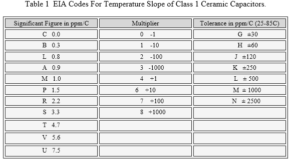
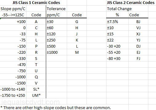
Table 1 shows EIA-RS-198 codes for Class 1 ceramic capacitors and specifies temperature range and capacitance drift tolerance over that range. It's rare to see anything but C0G.
So, for example, the ever popular C0G has a temperature drift of 0.0±30 ppm/C (+25C to +85C) and P3K has a temperature drift of -1500 ± 250 ppm/C. Tolerance only applies from +25C to +85C. From +25C to -55C the "-" figure is 1.25-4 times higher depending on the "Significant Figure". For example, C0G is ±30 ppm/C from 25C through 85C, but +30/-75 from 25 to -55C. Don't expect to see all possible combinations. Who would want a C0N for example? The EIA has a "preferred" list of some 200 parts, but only about two dozen are commonly available.
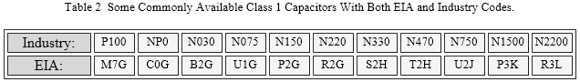
Industry commonly uses an "N/P" designation system that is obsolete, but is more intuitive, and more reflective of what is actually in production. The "N" is used for capacitors with a negative temperature coefficient, and a "P" for those with a positive coefficient. Manufacturers usually use both in their catalogs, while distributors' catalogs often use only the N/P codes. Purists righteously disdain the use of NP0 (an older military designation) when referring to C0G (an EIA specification) capacitors, however.
So, for example, an X7R would be usable from -55 through +125C and should change no more than 15% from its 25C value. One note, however; Class 2 and higher capacitors are affected by voltage and the above drift limits hold only at low applied voltage. Don't expect to find all possible combinations; X7R, Z5U, X5V,and Y5V are among the most common although other types are also seen.
Why use them if their electrical properties are inferior to C0G? Size and cost. You will rarely see C0G larger than 0.1 uF (at least as a standard product), but Z5U can be found as large as 22 uF, even in SMD. Poor as it is by C0G standards, a 22 uF Z5U can compete with the equivalent electrolytic in many high-frequency applications with a much lower ESR. As switching power supplies go ever higher in frequency, large ceramic capacitors look more and more attractive compared to higher ESR electrolytics, and some manufacturers make parts, both SMD and leaded, aimed directly at that market . On the other hand, advances in film production have allowed large low-voltage film capacitors to compete with ceramics in some applications. Some manufactures offer films as ceramic substitutes without even mentioning the dielectric, although it is almost certainly polyester.
As a rule of thumb, Class 1 ceramics (like C0G) can be used in many common analog electronics applications. Exceptions would be sample-and-hold circuits and integrators, where mediocre dielectric absorption is a problem.
Class 2 ceramics (like X7R) are best suited for coupling (DC blocking) and power supply bypassing. X7Rs can be used in some linear applications with care where performance and stability are of no great concern. It would probably be best to use the highest voltage rating practical to minimize leakage, which can vary a lot from part to part. Class 3 capacitors should be used only for DC blocking and P.S. bypassing, and even then, change in capacitance due to aging, temperature coefficient, and voltage coefficient must be taken into account. For the best characteristics from Class 2 and 3 ceramics, use the lowest K material that you can, and use them at a low percentage of rated voltage.
Class 4 are the barrier-layer or reduced-titanate ceramics. They may not have quite disappeared, but close to it. These ceramics have low breakdown voltage, high leakage and all-around terrible electrical properties. High Ks made them useful at one time but modern multilayer ceramics have largely made them obsolete.
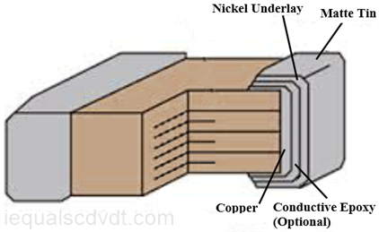
The end electrodes have been tin-lead over nickel, but other systems are occasionally used, such as silver-palladium over
nickel or gold over nickel. Silver-palladium is used where the parts are glued with silver-epoxy instead of being soldered
(rare). Silver-palladium is almost impossible to solder. Thanks to RoHS, the lead is disappearing and being replaced by
matte tin over nickel. A common option is an inner layer of silver-epoxy. Silver-epoxy is more flexible than metal plating
and make the capacitor less vulnerable to cracking from temperature cycling or board flexing.
The internal electrodes have traditionally been silver-palladium or palladium. These are call "precious metal electrodes"
(PME). The cost of palladium has been increasing dramatically so other metals have come to be used. Nickel and copper
electrodes are the wave of the future with their lower resistance and lower cost. These are called "base metal electrodes"
(BME). Note that PME capacitors are inherently non-RoHS compliant because the dielectric contains some lead.
The thinner the ceramic, the better. If you halve the thickness, the capacitance-per-volume (volumetric efficiency)
quadruples. The limiting factor is voltage breakdown. However, thinner also means more difficult to make reliably. At
present, manufacturers are making MLCCs with up to 100-1200+ ceramic layers with a thickness that go below 1 micron
depending on voltage rating. MLCCs with more and thinner layers are promised, the goal being to make the layers so thin
they are no thicker than needed for the system supply voltage. This may have happened by the time you read this.
However, as the layers become thinner, previously unseen failure/wearout mechanisms will come into play. MLCCs are
available as leaded devices, both as disks and as chip capacitors with leads, but SMD is where the real action is.
Because of ceramic capacitor's wide range of uses, ceramics (mainly SMD) are found in a number of special types. They
include:
Low ESR. This can be done in a number of ways. Some are wider than they are long. This also reduces ESL.
Low height, for use in things like smart cards, or to go under a RAM IC for power supply bypassing.
Special RF power arrays.
Special materials for microwave applications, like porcelain, silicon dioxide, silicon nitride, and other materials.
High precision C0G parts, to at least 0.5%.
High temperature operation, to at least 200C in C0G and X7R (and X8R). Some to 260C. Maybe even 300C.
High voltage, to at least 10 kV in SMD.
Non-magnetic. This means replacing the nickel.
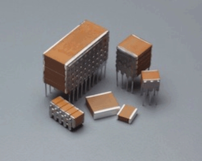
Multiple chip assemblies with lead frames (see below).
A number of end electrodes metals, both for soldering, and gluing with conductive epoxy.
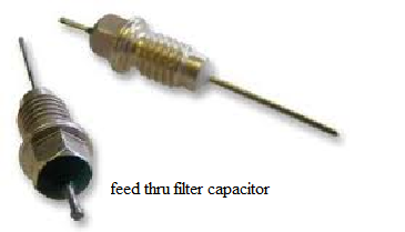
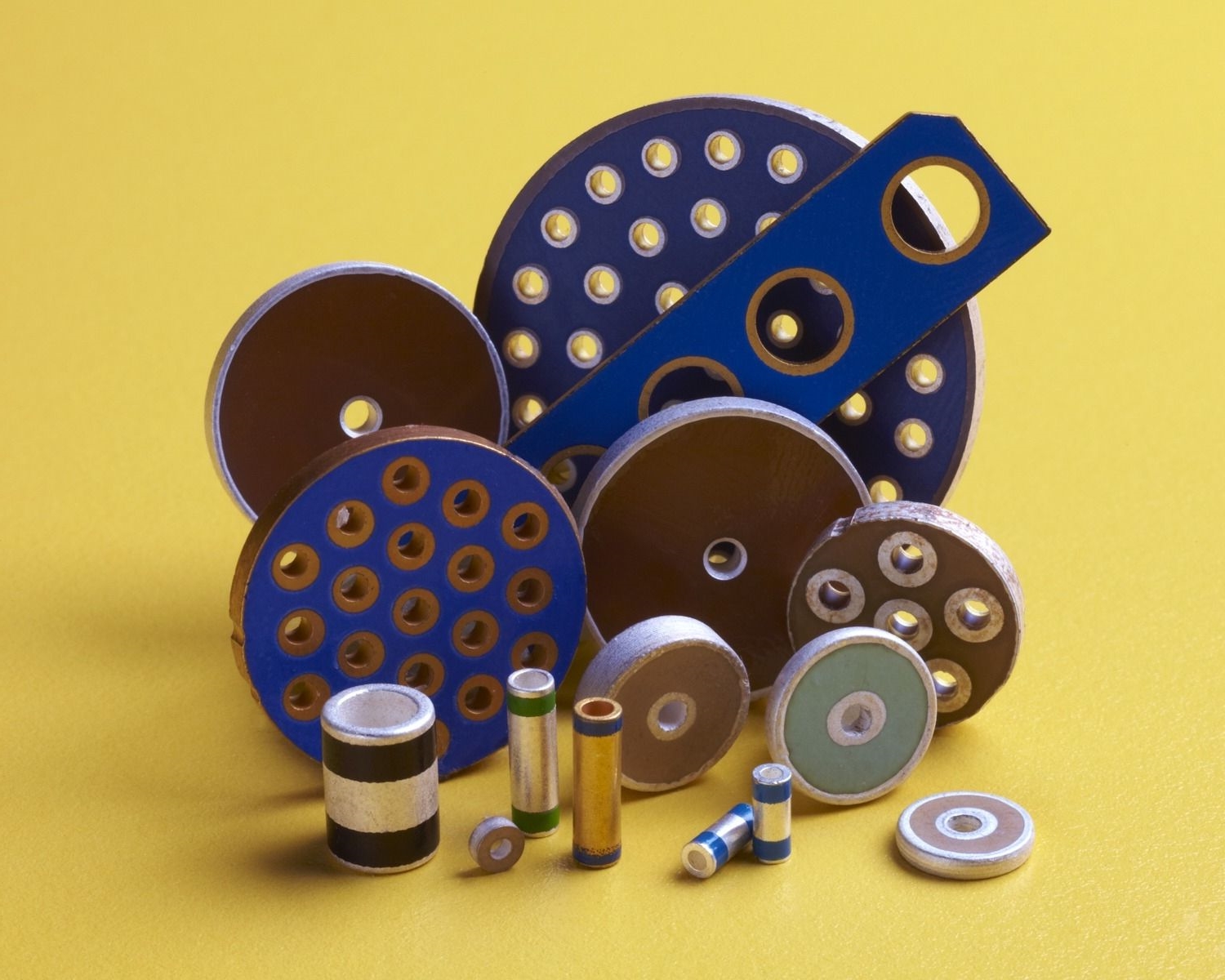
A variety of special sizes and shapes for applications like very high current RF, or microwave use. Some really
special shapes for filters in connectors, called planar, tubular and discoidal (see below). Feed-through capacitors for
bulkheads (see below).
Solderability. Most SMD parts are soldered by reflow soldering. A few boards must be soldered by wave
soldering, a more violent process. Don't assume that all SMD ceramics are suitable for wave soldering. Check with the
manufacturer.
And not to be forgotten: RoHS (pronounced "rose").
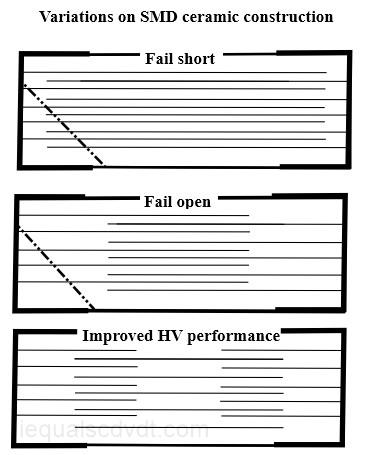
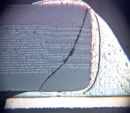
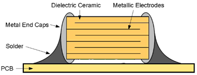
On the right are some variations on the typical SMD construction. Because ceramic capacitors are so brittle, cracks can
happen when the circuit board flexes or from improper placement when the board populated. The top is the usual
construction, which tends to fail short in case of a crack (bad). The middle one will usually fail open (better). The bottom
version is for improved high-voltage performance and also provides protection against a short. There are a number of
other design features that can improve voltage breakdown and ESR.

xxx