Reforming aluminum electrolytics: 

If aluminum electrolytic capacitors are stored unpowered for a significant length of time, over 1 year perhaps (some people say as little as 6 months, some say more like 2-10 years), the common wisdom is that some of the aluminum oxide dielectric will have dissolved and developed thin spots to the extent that the capacitor might overheat or even explode when power is applied.  This would be due to a large increase in leakage current.  Some manufacturers say the safe storage time depends on the capacitor temperature rating, with 85 C parts safe to store as little as 2 years and 125 C parts safe to store as long as 20 years (at 25 C).  One company simply says 5 years storage at room temperature.  How big a danger this is in the real world is a subject of some argument. Some people claim this is not a significant problem with capacitors built since the 1970s or 80s due to an improvement in the electrolytes, but this is almost certainly not true.  Manufacturers generally mention shelf life in their data sheets in terms of thousands of hours at some temperature during which the part will still meet certain specification of capacitance change, leakage change, or whatever.  Their numbers don't tell you how many hours of storage until they can't guaranty against catastrophic failure when the capacitor is powered up. 

The manufacturers of equipment with DC link electrolytics take shelf life seriously, and sometimes have a built-in function for "reforming" the capacitors if the equipment has been unpowered for too long.  This is sometimes called "precharging".  Adding a reforming function should not be too difficult.  All you should need is a small separate power supply with a current-limiting resister.  The built-in reforming procedure might not be suitable if the equipment has been idle for >2 years however, so a manual reforming procedure might be recommended.  See:

http://www.bonitron.com/PDFs/Manuals/D_M3628PCF_CMAN_02e.pdf 

So, what is reforming and how should you do it?  The idea is to apply a voltage to the capacitor, equal to the capacitor's rated voltage, but with a current-limiting resister in series that will keep the current to a safe level during the reforming period.  During this period the current will grow new aluminum oxide which will repair the oxide layer until the capacitor is safe to use again.  A DC meter measures the voltage across the resister to monitor the current.  It will start out high and slowly drop as the oxide layer regrows.  When the current has dropped as low as it will go and is now steady, the reforming process is over.  Or maybe not.  A common recommendation is to let the reforming go on for 1 additional hour for every year the capacitor was unpowered.

What should the starting current be?  I have almost never seen a logical number for this.  It should be possible to come up with a current that would work for any capacitor or capacitor bank, whether it be 10 uF or 100,000 uF.  Let's say 20 uA/1 uF (I'm just making that up but it's not an unreasonable number), but hardly anyone seems to think in those terms.  They tend to think in terms of some fixed value.  However, one manufacturer recommends a starting current of twice the rated leakage current.  That does sound like a reasonable idea.  MIL-HDBK-1131B has a recommendation.  It specifies a light bulb as the resister, which may or may not be a good idea. 

A different way is to use a fixed resistor and a variable power supply to get the starting current you want.  Another, easier, method is to power the equipment from a Variac.  Start the applied AC voltage low and slowly increase it over time. 

All this will only work if the capacitor is otherwise undamaged.  If the capacitor is very old and the electrolyte has lost its water, then the capacitor must be replaced.  If a capacitor has failed during operation, it is also beyond hope and must be replaced.  If the current does not drop to a "low" value in a few hours, replace the capacitor.  Below is a typical setup. 
Miscellaneous
This page covers a variety of issues that I wasn't sure where to put.
AVX recommends their MLO capacitors for sample-and-hold circuits, but they seem to be available only in very low values, <10 pF.  I rarely see sample-and-hold capacitors smaller than a few hundred pF.

It was claimed that Paralene had an even lower DA than Teflon.  I haven't seen actual numbers, and these capacitors are long obsolete. 

MIL-C 19778  One opinion on how to measure DA. 
IEC/EN 60384-1  Equivalent to MIL-C 19778. 
Using capacitors to replace a transformer: 

To save the cost of a transformer, some people use a capacitor as a near lossless voltage drop in AC line-powered equipment.  Circuits like this are probably practical up to a few hundred mA.  At one time many line-powered smoke detectors for example, were designed this way.  This may not be true any more.  Smoke detectors can be made so low powered that a power resister of <5 watts should do as well and be cheaper.  Also, the capacitors were causing problems. 

Using a capacitor instead of a transformer in a little tricky.  I have seen pictures of some of these smoke detectors after the capacitor failed short and went up in flames.  The designers didn't understand that using a 150 VAC capacitor on a 120 VAC power line is not a great idea.  The power line is subject to disturbances like high-voltage spikes that can destroy a capacitor in time.  How about a 250 VAC capacitor?  Or maybe a 600 VAC part will be reliable? Or maybe not.  The Japanese used small  capacitors in classic audio equipment, to "ground" the circuit low to the power line, and they were1500 VAC.  An even better idea is to use X2 capacitors which are made for this sort of thing.  If you use a non-X2 capacitor, you should at least use a polypropylene metallized-film part for their self-healing capability. 

In the picture below, the "Basic Version" shows how not to do it.  In the "Better Version", R1 is added as a bleeder resister to discharge C1 for safety.  C1 is now an X2 capacitor, and the fuse is added in the very unlikely event C1 fails short.  R2 is often used, probably to limit fast spikes.  There are any number of variations on this circuit.  The chart shows the impedance at 60 Hz for various values, and the nominal cost for several of the parts in small quantities. 

Remember that you lose the safety of ground isolation, so make sure users can't get their fingers where they can touch any of the circuitry. 

http://ww1.microchip.com/downloads/en/AppNotes/00954A.pdf  One opinion. 


This is a guide to measuring it. 

1)  The the test capacitor (C) is charged at some voltage for a number of minutes (Tc).  The charging time might be one or
more minutes. 

2)  The Charging Switch is opened, and the Discharge Switch is closed, for perhaps 10 seconds (Td).

3)  The Discharge Switch is opened and the voltage on C is monitored with a DVM or oscilloscope for several minutes. 

4)  The ratio between the original voltage and the final voltage is calculated, in percent.  This is the dielectric absorption
number. 

5)  MIL-C-19978 says charge time = 1 hour, discharge through a 5 ohm resistor for 10 seconds, the final voltage is recorded
after 15 minutes.  This is the method many people prefer to use.  This is fine except that it might be better to record a curve over
the 15 minutes.  A single number will not necessarily tell you all you need to know.  Some people will be more interested in what
happens in the first few milliseconds.  See standard MIL-C-19978  for the details, it even has a picture. 


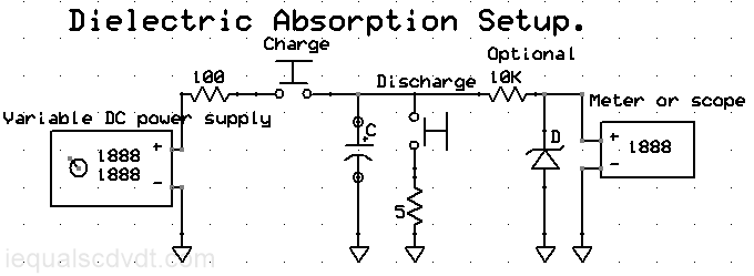
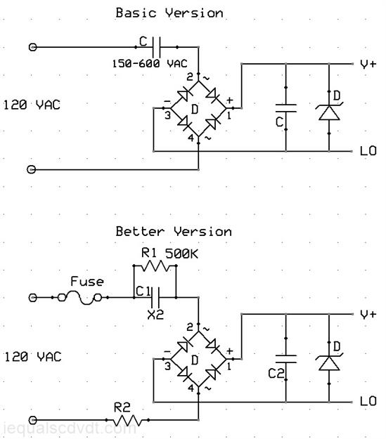
The circuit below has everything you should need for a DA measurement.  The 100 ohm resistor limits the charging current to a
level that won't damage the capacitor C or the switch. If the test voltage you use is high enough to damage the meter or (more
likely) the scope, the 10K resister and the zener diode should protect it.  The resistors must be made for high-voltage operation,
your basic RN55, 1% parts, won't do.  Several RN-70s or something wire-wound maybe. 

However, don't expect this test to give you consistent and part-to-part repeatable numbers.  What you will get will have some
dependency on the history of the part you are testing.  By history I mean applied voltages and temperatures.  One possibility
might be to short the capacitor for an extended time and at an elevated temperature to clear out any trapped charge before
testing.

Apparently, at one time one manufacturer offered Teflon capacitors selected for low DA. Why bother with all this?  If you are
using low DA caps in a circuit you might actual need to measure the DA.  DA varies significantly part to part and batch to batch. 
In fact it varies enough to cause some doubt about the exact DA numbers given to various dielectrics.  A number of circuit
methods have been devised to compensate for the affects of DA, if only approximately.  Many of these have been patented. 

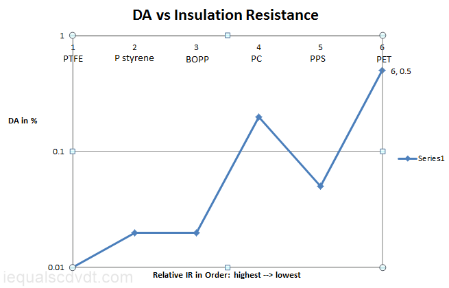
The DA of a dielectric material tends to track with the leakage figure, if not perfectly.  This suggests that the DA number you get
might be different for a higher voltage capacitor than lower voltage capacitor, assuming the test voltage is the same.  A good
experiment to try, but I don't know that anyone has.  There have been reports that the DA of ceramic opamp packages can
cause problems for some analog circuits. 

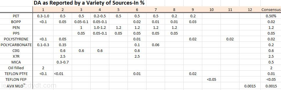
The DA numbers below are for room temperature.  DA is very temperature temperature sensitive however.  Different dielectrics
behave differently, but The DA might be 20 times higher at 100C than at 25C. 

If you found it necessary to build a super low DA capacitor in the 0.001-0.1 uF range, how would you do it?  Vacuum makes
the highest resistance dielectric, followed by gasses.  These would be very difficult to work with.  There are patents on board-
level air-dielectric capacitors, but intended for microwave work, which means very small values.  There are some metallic
oxides that have very high resistance, and these might have possibilities.  Below are the dielectric absorption numbers from
about a dozen sources.  They don't entirely agree with each other. 
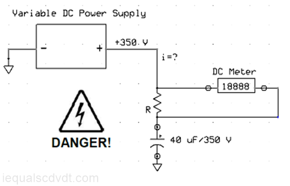
If you are working with voltages >35 volts or so, use appropriate care.  If you electrocute yourself, don't blame me.   A
capacitor like this can remain charged for a long time after being disconnected.  In some cases, if you short it (through a resister),
it can recover enough of its voltage to be lethal, thanks to dielectric absorption. 


Audio capacitors: 

The "golden-ear" audio crowd says it can hear capacitors.  That is, audio equipment will sound different when built with different
kinds (or even brands) of capacitors.  These people also think they can hear different brands of solder and line cords, and who
am I to say they can't.  Different dielectrics will have an affect on signals in the audio range, but  it's not clear at what point the
ear-brain combination can hear those differences.  A number of companies make golden-ear audio capacitors that use
dielectrics and electrode foils that may not be found in more common parts.  They include bee's wax, Teflon (2 kinds), copper,
silver, tin, oil in paper, and even fluorinert, as well as the usual polystyrene and polypropylene.   Several mainstream companies
also sell what they call audio-grade capacitors. 

Audio capacitors are used in three places.  How would you choose capacitors for each application?

The signal path, low-level equalization, tone controls and DC blocking:  The ideal capacitors should not be subject to
voltage modulation, that eliminates the class 2 and 3 ceramics.  They should also have minimal dielectric absorption.  That
eliminates C0G ceramics, most film capacitors and others.  The best would be polystyrene, polypropylene and Teflon.

Power filtering electrolytic capacitors:  They should be large, but that's no problem.  They should have fairly low ESR
and they should be reliable.  I would probably go for low ESR and high-temperature parts for long life.  Just for overkill, I
would parallel them with a bunch of polyester films (or maybe X7Rs) for lower ESR.  DC link capacitors are showing up in
some designs.  They have lower ESR and ESL than ordinary capacitors. 

Speaker crossover capacitors (speaker level):  There is a general agreement that you should never use electrolytics. 
Polypropylene would be better but polyester is probably more common.  If it's not practical to avoid electrolytics, polymer-
aluminums might be better that conventional aluminums, assuming you can find the right values and voltages. 
A common argument is over whether or not you can make a non-polarized electrolytic capacitor by putting two polarized electrolytics back-to-back.  People have been doing this for years, with no problems.  Total capacitance will be half as much as the value of the individual capacitors (assuming they are equal), as you would expect with capacitors in series. 

http://electronics.stackexchange.com/questions/21928/can-you-make-a-non-polar-electrolytic-capacitor-out-of-two-regular-electrolytic?rq=1 
https://linearaudio.nl/cyril-batemans-capacitor-sound-articles
http://www.linearaudio.net/  A motherload of audio information. 
http://www.angelfire.com/electronic/funwithtubes/Restore_cap.html
http://www.enjoythemusic.com/diy/0708/capacitor1.htm 
http://www.conradjohnson.com/It_just_sounds_right/cap_upgrades.html
http://www.partsconnexion.com/index.html  The mother load of expensive capacitors. 
http://lampizator.eu/UPGRADE/CAPACITORS/capacitors.html  Lots of great pictures of old European capacitors. 
http://www.analogmetric.com/index.php  Lots of high-end audio parts and kits. 
http://www.elna.co.jp/en/capacitor/onkyou/silmic.html
http://www.designers-guide.org/Modeling/da.pdf
http://www.keith-snook.info/capacitor-soakage.html
https://cdr.lib.unc.edu/indexablecontent/uuid:9548dfd5-f6b3-48de-aa97-c562c379949c
http://www.datasheetarchive.com/files/national/htm/nsc03883.htm  The classic DA article by my hero, Bob Pease. 
http://electronicdesign.com/analog/whats-all-soakage-stuff-anyhow  Bob Pease again.  The site also had more of Bob Pease' articles. 
http://www.openelectrical.org/wiki/index.php?title=Dielectric_Absorption_Test  Insulation resistance testing using DA. 
http://www.existest.com/appnotes/Baker/InsulationFaultZone.pdf  
Double click to edit
http://www.cde.com/resources/technical-papers/capability.pdf  Talks about military grade electrolytics with low-gassing electrolyte and "near-hermetic" case.  Also covers storage life in general. 
http://www.illinoiscapacitor.com/pdf/Papers/reconditioning_aluminum_electrolytic.pdf These guys take reforming serious and they should know. 
Dielectric Absorption (DA): 
http://www.everyspec.com has government standards for free under one roof and is very easy to use.  IEC/EN 60384-1 is the European equivalent and works the same (but I haven't actually seen a copy).