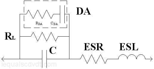
Above is an electrical model of a capacitor, the most common one anyhow. It´s a fairly good model for understanding how capacitors will behave under most conditions, but real capacitors are a bit more complicated. It does not, for example, show the temperature and frequency dependence of the various elements. Also, the model does not show all the parasitic elements that may be important above the resonance point. This would be important in RF/microwave applications.
Some manufacturers make SPICE models of varying complexity available that better reflect very high-frequency behavior, such as secondary resonance points. SMD ceramics are typically represented with two inductors rather than one. The 3-dimensional nature of tantalum capacitors forms a sort of distributed R-C ladder network that limits their frequency response. A good tantalum model will use about a dozen components. Go to http://www.kemet.com for Kemet´s excellent capacitor SPICE program for more information. TDK has a frequency dependent parasitic element called "Hysteresis Derived Resistance" in their models of their Class 2 ceramics. HDR is in parallel with the insulation resistance.
C is the primary capacitance, the one printed on the label.
R L is the leakage.
ESR is the equivalent series resistance. ESR is generally made up of three components, the lead and end-termination resistances, the electrode resistance, and dielectric loss. The model implies that ESR is constant with frequency. Actually, the skin effect can be a factor in high frequency performance, while the dielectric loss is frequency and temperature dependent for most materials. For aluminum electrolytics, the ESR increases somewhat at low frequency due to electrochemical affects, but the change is small compared to Xc.
ESL is the equivalent series inductance, mostly of interest to RF and microwave people.
DA is the dielectric absorption. The RDA-CDA model is the one most commonly shown (there are others). A more realistic variation is an infinite series of RDA-CDA networks, all in parallel. In each succeeding network, the R would get larger and the C smaller. The sum of the CDA capacitors is substantial, somewhere on the order of magnitude of the primary capacitance (based on rather limited research however).
You can add a zener diode across C. This makes model look more like an electrolytic capacitor.
Philosophically, it should be noted that the models are purely functional, and give limited insight into the underlying physics.