Capacitor Types:
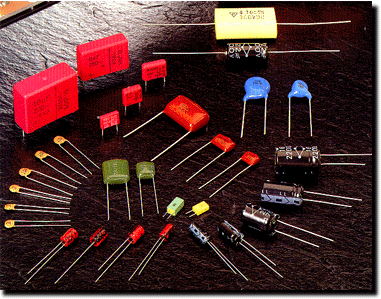
You can roughly divide all capacitors into four groups: film, ceramic, electrolytic, and miscellaneous.
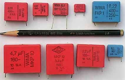
Film Capacitors:
Film includes a variety of polymers, such as polyester, polycarbonate, Teflon, polypropylene, and polystyrene. Traditional
film capacitors were only available in modest sizes, <10 uF. In recent years, film capacitors have sought to leverage their
superior longevity compared to electrolytics, to move into some applications that call for much larger parts, even to thousands
of uF. Film capacitors come in two broad categories, film-foil, and metallized film. Film-foil capacitors are made of
alternating layers of plastic film and metal foil, while metallized film capacitors have the metal vacuum deposited directly on the
film. In general, film-foil is better at handling high current, while metallized film caps are capable of self-healing. Various
hybrid types can also be found.
Pros: The film capacitors mostly have reasonably well behaved electrical properties and offer many tradeoffs of
performance and cost for people with precise requirements. The main parameters of interest include capacitance vs.
temperature, dissipation factor, and dielectric absorption. Their main virtues include low leakage, low voltage sensitivity, and
low aging.
Cons: The main drawback of film capacitors is their low dielectric constants (K), which is only partly offset by their
relatively good breakdown voltages. That means that film capacitors are physically large for their capacitance. Their Ks vary
from a low of about 2.2 for Teflon to about 8 for PVDF (rarely used). Unfortunately, the rule-of-thumb is that the higher the
K (and therefore the smaller the size), the worse the electrical properties tend to be. Film capacitors have not made an
entirely graceful transition into the age of surface mounting. While some film dielectrics are suitable for surface mounting, most
can't withstand the heat of soldering. Even polyester, the toughest of the traditional films, is barely good enough. However,
capacitor makers have responded by developing several new dielectrics. SMD film capacitors are not as widely second-
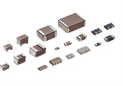
Ceramic Capacitors:
Ceramic capacitors offer a broad range of size vs. performance tradeoffs and are easily the most popular in numbers sold.
Ceramic capacitors are available from < 1 pF to 1000s of uF.
Pros: The main virtue of ceramic capacitors are their relatively high dielectric constants. This can vary from C0G with
a K of up to 60, which has excellent electrical properties but is relatively large and expensive, to ceramics with Ks in the tens
of thousands but with very poor electrical properties. Large- value ceramics can replace electrolytic capacitors in high-
frequency applications like switch-mode power supplies because of their lower ESR. Ceramic capacitors are especially
suitable for surface mounting due to their heat resistance, mechanical integrity, and the ability to make them in very small
packages at low cost, for portable equipment. This has greatly added to their usage. To some extent ceramics are slowly
displacing other types of capacitors.
Cons: Low breakdown voltage means that the low-K ceramics (Class 1), the ones with the good electrical properties,
have poor volumetric efficiency, and are usually found only in small values. High-K ceramics (Class 2 and higher) have poor
electrical properties, which are highly dependent on temperature, voltage, and frequency, plus a significant aging rate. Unlike
many other capacitors, ceramics have no self-healing mechanism. This means that manufacturers must maintain a high level of
quality control over the dielectric. Ceramics are most cost affective in small sizes at present. Very large ceramics are a bit of
a challenge, especially in SMD.
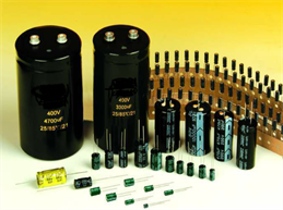
Electrolytic Capacitors:
"Electrolytic" means any capacitor that requires a conductive layer between the dielectric and one electrode. In the original
electrolytic capacitor, the layer was an actual electrolyte, a conductive salt in a solvent. Some electrolytic capacitors today
don't actually use an electrolyte, but the word is still commonly used, to the annoyance of some. Electrolytic capacitors are
made by growing a oxide film, the dielectric, on a metal, the anode, by electrochemical means. The films are very thin with
fairly high Ks (roughly 10-25) which make for a lot of capacitance in a small package. The resulting devices can pass current
only in one direction, the other direction would strip the oxide off the metal. Because of this, the metals are sometimes called
"valve" metals. The metals presently used are aluminum, tantalum, and niobium, but zirconium, tungsten, and titanium are also
valve metals.
Pros: Electrolytic capacitors are best used when you need a lot of capacitance in a small space and at a reasonable
price, such as power supply filtering, or energy storage. They are available in sizes far beyond that of other capacitors.
Aluminum electrolytics are presently available from 0.1 uF to several F. I have no idea why someone would use a 0.1 uF
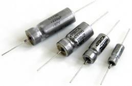
electrolytic capacitor however. Tantalum electrolytics are available from 0.1 uF to a few thousand uF.
Cons: Marginal electrical properties means that these capacitors must be applied with care. The parameters to watch
include leakage, service life vs. Temperature and voltage, ESR, ESL, and low-temperature performance. Long-term
reliability is a big deal. Unlike other capacitors, electrolytic capacitors are not inherently non-polar, but non-polar types are
available. Electrolytics are widely available in SMD packages, at least in moderate sizes, but users complain of more
reliability problems than with through-hole styles.
Miscellaneous Dielectrics:
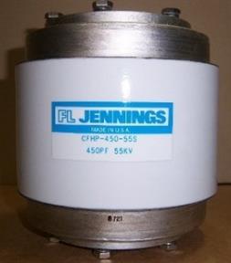
Miscellaneous capacitors include materials like glass, mica, porcelain, gases, and even vacuum. A few exotic dielectrics like
silicon dioxide and sapphire are used in niche applications like microwave capacitors and trimmers. Some are available in
surface-mount packages.
Pros: The electrical properties of the miscellaneous capacitors are generally most similar to film capacitors. However,
they all have electrical properties that make them useful in some special applications.
Cons: These materials also have Ks similar to plastic films so they have no great advantage in size. Except for mica
and silicon these capacitors are commonly available only in small sizes, <1 uF. They also tend to be more expensive than
other capacitors of similar size, in some cases much more expensive.
Anyone who has corrections or additional information is more than welcome to contribute. If you have an idea for additional
topics, expansion of existing topics, if something unclear, if you see an outright error, whatever, let me know. The site is still in
its infancy, and I don't really have a clear vision of what it will grow into. I would especially like to hear from the capacitor
engineers of the world, they are the people who should have written this FAQ, but didn't. So far, my attempts to get these
people involved has had limited success. It would be nice if an expert with specific knowledge would offer additional or
corrected information not available to me.
What is good or bad about the site?
What would you like to see added?
Is your interest mainly for personal or business reasons?
Were you looking for something in specific, and did you find it?
People who helped with this site:
badbob@iequalscdvdt.com *: Research. Presently being treated for a long-standing capacitor fetish.
Dave D.: This was all his idea

CapSite 2023
Introduction To Capacitors 2.7
"...has many omissions and contains much that is apocryphal, or at least wildly inaccurate..."
Douglas Adams
The Hitchhiker's Guide to the Galaxy
This site started out as a simple exercise in web page making that sort of got out of control. Once I started writing, I found it hard to stop.
The last release was in 2009. For this one I made some updates, corrections, and additions but I can't guarantee everything is up to date. I wasn't willing to put that much effort into it.
A few disclaimers: Some of the information in this "FAQ" should be considered to be generalities. Material source, processing and capacitor construction can greatly affect a capacitor's electrical properties. Different manufacturers tend to have different opinions on the characteristics of their dielectric materials. For example, most show polystyrene as having a slight negative temperature slope while at least two show it as being slightly positive. When in doubt, contact the manufacturer to guarantee that the parameter you are interested in is good enough for your needs. This is especially true when using the various graphs. These should be used more for comparing different capacitor types than for hard design data. That is best obtained from individual manufacturers. In some cases, construction variations so distort the basic capabilities of the material that it seemed best not to include graphical data. When using charts of dielectric characteristics, it is best to look at a number of sources.
Much of the available quantitative information of capacitors is not very complete. Dissipation factor vs. temperature is almost always shown for 1 kHz. DF vs. frequency is normally shown for 20C or 25C. If you want to know the DF of polyester at 95C @ 20 kHz, you will probably be out of luck. Certainly the manufacturers have some of this sort of information (the good ones anyhow), but it is rarely published. It´s the rare hobbyist who needs to know that sort of thing however. If you are looking for information on just the dielectric, as opposed to a finished capacitor, the material manufacturers often have very complete information.
On the other hand, as consumer electronics moves into GHz frequencies, designers need information on dielectric behavior that may not yet be available.
Some capacitor parameters are difficult to measure with good absolute accuracy. An instrument for measuring dissipation factor for example, may give good relative results for comparing different capacitors, but not agree with another brand of instrument on the actual numbers.
The information given here is as good as I can make it, which probably means it has its share of errors. There are also many omissions; my main interest is in analog electronic applications so that is how this FAQ is oriented. There is some mention of high-power capacitors, but sort of thing is too specialized for good coverage here. This is meant as an introduction to capacitors, not a book. This FAQ is aimed more at students, hobbyists, scientists, and new engineers than at electronics "insiders". It does not (yet) contain a dictionary of terms, that has been done by other people.
This is also a good place to note that some limitations mentioned, like size, voltage ratings, packaging, temperature ratings, etc., will usually only apply to high-volume capacitor manufacturers. There are specialty manufacturers who can make most anything you can think of.
What is a Capacitor?
A capacitor is a energy storing device made up of two parallel conductive plates separated by an insulating (dielectric) material. When a voltage is applied across the plates, the electric field in the dielectric displaces electric charges, and thus stores energy. It is assumed that there are no free charges in the dielectric (at least in the ideal case), and that while they are displaced, they are not free to move around as in a conductor. The closest analogy in the mechanical world is probably energy stored by a spring. Dielectrics come in two types, "polar" and "nonpolar". Molecules where the "center-of-gravity" (as it were) of the negative and positive charges are at the same point are nonpolar. If this isn't the case, the molecule is polar. H2O for example, is polar(K=80), but H2 is nonpolar (K=1.2 as a liquid).
The plates may be actual metal plates of various shapes but are most often in the form of metal foil or a metal film deposited on the insulating material. Since the first capacitor was invented, the Leyden jar, almost every conceivable dielectric material and form has been tried by someone. Wax, paper, plastics, ceramics, glass, oils, minerals, electrochemical films, air, etc., either alone or in combination such as paper/wax, paper/epoxy, plastic/plastic, paper/oil, plastic/oil have been used, to name just a few. Some people separate capacitors types into "electrostatic" and electrolytic". This is really an artificial distinction, more of a construction detail than a fundamental difference.
Characteristics:
The reason for the many types of capacitors is cost and performance. Different capacitor types are better at different things. No capacitor is just pure capacitance and there is no perfect capacitor at the perfect price. Every capacitor type has a number of parasitic elements associated with it such as leakage, ESL, and ESR , plus special quirks all its own. This makes it tricky to select just the right capacitor for every application.
Factors of concern to the user include (but are not limited to): See Graphs page.
Aging rate: mostly of concern for ceramic capacitors although all capacitors age, however little. Film capacitors typically age less than 1% over their life, while some ceramics may age >10%. With films at least, manufacturers tend to disagree over exact numbers. This is probably due to differences in test methods.
Special Updates:
Anyone who has information on Chinese standard GB/T 2470-1995 (previously GB 2470-81), please send it along.
Anyone who has information on GOST 11076, please send it along.
https://www.youtube.com Loads of fun with capacitors.
NASA: For pictures for the whiskers section of Reliability page. Other pictures were obtained indirectly through NASA.
WIMA: For pictures on the Film Construction page, and on other pages.
Paktron: For some background material and graphics on stacked-film capacitors. Now part of Pancon.
Oren Elliott Products: For background material and pictures on air-variable capacitors.
Jennings Technology: For background material and pictures on vacuum and gas capacitors.
Eichhoff Electronics: For pictures of line-filter capacitors and the line-filter modules they are used in.
Sinclair Manufacturing: For pictures of hermetic packages.
https://www.google.com/ Good for searching the internet, but don't expect to find this site with it.
http://www.bing.com/ Another favorite tool, it's my favorite for finding images.
https://duckduckgo.com/ And another. In some ways I consider it the best of the three. I find things there I don't elsewhere.
http://www.wikipedia.org/ The first place to go when you can't find it here.
Google Scholar: The best source of research documents of all kinds. Most sources charge up to $40 per full-text article, but Scholar directs you to free sources if available. I'm not paying $40 for anything when this site makes me no money.
Carey Holzman of Computer Performance Specialists (Phoenix, AZ) For pictures of "exploded" capacitors on the Leaky Caps page.
John Woodgate of J. M. Woodgate and Associates: For considerable help with the Line-Filter Capacitor section.
This site Copyright © 1999-2023. All rights reserved.
Individuals may copy portions for personal use only.
All trademarks are property of their respective owners.
Links to other sites are not an endorsement of their information or products.
Date of last change: 12/28/22. Changes both major and minor, added or eliminated some links, and some additional information.
The editor did some sort of damage to many of the links which is difficult to work around, even with backups, and I have been
slowly repairing the damage as much as possible.
* In a bit of bad news, my company was purchased by a conglomerate (Danaher) and at the end of July of 2002 I became
polyester, polypropylene, BOPP, buy, mica, Teflon, FEP, PFA, PTFE, ceramic, class 1, class 2, electrolytic, tantalum, PVDF, film,
vacuum, X1, X2, Y1, Y2, dielectric, trimmer, polystyrene, aluminum, esr, esl, capacitor, capacitance, China, symbols, insulation,
leaky, oil, frequency, line, filter, PCB, model, constant, link, DC, AC, aging, variable, glass, silicon, paper, C0G, X7R, NP0,
polysulfone, fluorene polyester, iec, eia, jis, voltage, SMD, polysulphone, NASA, UL, CSA, epoxy, EMI, RFI, CENELEC, EN,
Counterfeit, porcelain, temperature, air, http://my.execpc.com/~endlr/, reliability, symbols, meter, vacuum, sound, audio, silk, charge,
condenser, Genteq, variable, wax, whisker, zinc, capsite 2009,
http://my.execpc.com
Capacitance vs. Frequency: Determined by both the dielectric and construction details.
Reliability: Reliability and expected lifespan are of special concern in high-temperature, high-current, and high-voltage applications. However, capacitors used in more ordinary applications also have reliability issues.
Surge current capability: Of concern for high-current pulse applications. Manufacturers will specify a maximum current or a maximum dV/dT (in volts/usec.) for capacitors rated for high-current applications.
Temperature limits: Some dielectrics are limited to as low as 85C operating temperature while others can go to the 200-400C region.
Voltage limits: Both operating and surge. Both operating a short term.
Radiation: Capacitors can be damaged by radiation, but this probably not a problem unless you are sending a space probe to the outer planets. In that case you probably want glass capacitors. They have the ultimate resistance to radiation. In general, glass, ceramic and mica capacitors are very resistant to radiation while plastics have various levels of lesser resistance and electrolytics have the least.
Packaging and construction: Construction details and sealing methods can have a significant impact on performance and reliability. Most capacitor types require that air and moisture are sealed out to prevent degradation or contamination of the dielectric and corrosion of the metal film. The best Military-grade capacitors may be hermetically sealed in metal and glass. Lesser types may be molded in plastic, dipped in epoxy, or inserted in a plastic case and sealed with epoxy or urethane. The moisture absorption of the dielectric dictates the encapsulation methods allowed. As surface mounting of components replaces through-hole construction, a new problem faces the designer: can you get the capacitor you need in a surface mount package? Some capacitor types, like ceramics, are well suited to surface mounting. Others, like polystyrene and polypropylene, do not stand up to the heat of soldering and are not available for surface mounting.
Markings: It can sometimes be a challenge to determine the characteristics of some capacitors from their markings. This partly due to size limitations, partly to a lack of universally followed standards, and partly to the failure to consistently follow the standards that do exist.
Mounting options: Large axial electrolytics generally need be held down against the circuit board, either by a cable tie or some kind of glue.
Noise: Mostly of concern for electrolytic capacitors, due to leakage.
Insulation resistance (IR): Seen as a resistance in parallel. This is referred to as "insulation resistance" when the leakage is very low (film capacitors), and as "leakage current" when the leakage is high (electrolytics). Electrolytic capacitors may have the most leakage, but it is also of concern for film capacitors in some analog applications (integrators, sample-and-hold circuits). For films, the lower the dielectric constant, the higher the insulation resistance tends to be. Data sheets normally state it in megohm-microfarads. To determine the IR for a given capacitor, divide the M-uF value by the actual capacitance. Although film capacitors and C0G ceramics have the best IR, all things being equal, low-quality ceramics can still work in some leakage-sensitive applications if the value is low, the voltage rating is high, and you can live with their other shortcomings.
Line filter capacitors: As a matter of safety, capacitors used to filter line (mains) power for electronic equipment, must meet strict performance requirements. The Europeans have lead the way in this, while American and Canadian requirements have been more lax.
Humidity Resistance: High humidity can have a significant affect on film capacitors. Increasing the ambient humidity from 50% to 90%, for example, can cause a capacitance change from as little as 0.5% to as much as 3% depending on the dielectric. The change is temporary unless actual corrosion results. The time it takes to make the change (hours to weeks) depends on how well the capacitor is packaged. Boxed capacitors for example are much better than dipped. The increase is probably because water has a very high dielectric constant, about 78. Tantalum and ceramic capacitors have also been reported to have failure problems with high humidity. Humidity also has an affect on higher voltage capacitors like line filter caps.
Moisture eventually diffuses through the plastics used to seal capacitors, so hermetic capacitors would not have problems with moisture
Frequency range: Some capacitors, like mica and C0G ceramic are usable to the GHz range. Others, like tantalum and polyester, become unusable somewhere in the 100 kHz to 1 MHz area (depending on construction details) due to loss of capacitance and increase in dissipation factor.
Dissipation factor vs. temperature:
Equivalent series resistance (ESR): mostly of concern in high-frequency power applications and for power-supply filtering in high-speed digital systems. ESR is measured at different frequencies, depending on how a capacitor will be used. For cheap electrolytics this will be 120 Hz, for high-quality tantalums, it will usually be 100 kHz. Although measured in ohms, it is not independent of frequency, and in electrolytics, is somewhat higher at low frequency than at high frequency.
Equivalent series inductance (ESL): seen as an inductance in series. Mostly of concern for power-supply filtering in high-speed digital systems, and in RF applications.
Dissipation factor (DF): Of concern for AC power applications. DF is usually expressed in % or in ratio to unity (1% = .01). DF is equal to ESR/Xc . Actually, this is an approximation which ignores Xl, but it is usually close enough. Like most everything else about capacitors, it changes with time, frequency, and temperature. DF is the result of three loss factors. Metal losses (the resistance of the leads, end terminations, and the metal foil or film), the insulation resistance (mostly very small), and the dielectric losses. For film capacitors, film-foil types will have a lower dissipation factor than metallized film, especially at high frequency, because the metal losses will be lower.
Dissipation factor and value vs. applied voltage, mostly of concern for Class 2 (and higher) ceramic capacitors.
Dissipation factor vs. frequency:
Dielectric absorption (or DA): Sometimes called "soakage", "voltage retention", and other things. In high-voltage power cables it´s called "return voltage". A capacitor, once charged, stubbornly retains part of the charge, even after being discharged (shorted for some number of seconds), as if it had "soaked" into the dielectric. DA is modeled as an infinite series of RC networks in parallel with the primary capacitance, where the Rs are mostly very large and the Cs are smaller than the nominal capacitance. DA is a source of error in precision integrators and sample-and-hold circuits. Large high-voltage oil-filled capacitors (exceptionally high DA) can be shorted, yet retain enough charge to be dangerous. They are normally shipped with a short across the terminals that should not be removed until the part has been installed. High-voltage capacitors in TV sets are also still dangerous after being discharged, as is the parasitic capacitance in large oil-filled, high-voltage transformers and some high-voltage cables. There is a "standard" test for DA . The capacitor is charged to some voltage for several minutes (often 100 volts, but others can be used), and is then shorted for several seconds. After several minutes, the recovered voltage on the capacitor is read using a high impedance meter. The DA is expressed as the ratio between the recovered voltage and the charging voltage, in percent. MIL-C-19978D calls for a 5 minute/5 second/1 minute sequence. These tests are useful for comparing dielectrics, but don't really tell you just how a capacitor will perform in your application. In particular, the difference in DA of various dielectrics as seen one minute after the short is removed does not necessarily precisely correlate with the difference in DA as seen in the first few 10s of ms. In general, Teflon, polystyrene, and polypropylene are the best (as low as 0.02%), while the electrolytics, high-k ceramics, and oil-filled are the worst (1% on up). Impregnated film caps tend to have a DA that reflects the impregnant more than the film. Given the RC model for DA, it would make sense that the dielectrics with the highest insulation resistance (which also tend to have the lowest dielectric constant) would have the lowest dielectric absorption. There is also a significant difference from part to part. However, while the RC model is useful for predicting how DA will behave, it does not reflect the underlying physics. See Space Charge. Also see: http://www.national.com/rap/Application/0,1570,28,00.html
Capacitance vs. Voltage: Mostly of interest for Class 2-4 ceramic capacitors, and for some glass types.
Cost and availability:
Current-carrying capacity: Of concern when the capacitor must handle high alternating current which would cause self heating. This a problem for electrolytics, and for film and ceramic capacitors used in high frequency and/or high current applications. Manufacturers often have guidelines.
Capacitance vs. size (or "volumetric efficiency"): Mainly determined by the dielectric constant (K) (sometimes called "permittivity") of the dielectric and its voltage breakdown vs. thickness. For a given dielectric, size tends to vary as the square of the voltage rating. This is a crude approximation however. It assumes that the dielectric makes up most of the volume of the capacitor. In some capacitors, the packaging and associated materials actually makes up most of the volume.
Capacitance Drift vs. Temperature: Normally given as ppm/deg C. Every dielectric has a different temperature slope. This can be as low as +- 30 ppm/C for C0G ceramics (even +-15 ppm/C for special porcelain RF capacitors) to thousands of ppm/C for electrolytics and some plastic films. An old trick for getting reduced drift is to parallel two capacitors which have opposite temperature drifts, such as polyester and polypropylene, or polystyrene and polycarbonate. The temperature drift for a given dielectric can vary from one manufacturer to another however, making this technique uncertain. Polycarbonate for example, is shown by some manufacturers to have a slightly positive slope, and slightly negative by others. Caps with mixed dielectrics exist, but are not common.
